
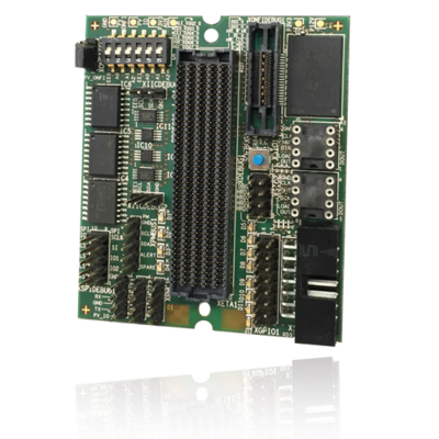
proFPGA ONFI Flash Board
Technical highlights
- ONFI flash
- 128 Gbit: MT29F128G08AMCDBJ5-6
or - 256 Gbit: MT29F256G08CBCBBJ4-37
- 128 Gbit: MT29F128G08AMCDBJ5-6
- 512 Mbit quad SPI flash (S25FL512SAGMFI011)
- 1 Mbit NVSRAM (CY14V101Q3)
- 1 Mbit quad SPI MRAM (MR10Q010SC)
- Debug interface with 38-pin MICTOR connector
Product Summary
The proFPGA product family is a complete, scalable, and modular multi FPGA solution, which fulfills highest needs in the area of FPGA based Prototyping. Because of its modular and scalable system architecture, the user has maximum flexibility and reusability.
Part of this modular and flexible system concept is the proFPGA ONFI Flash board. This daughter board occupies one extension site of the proFPGA system and offers 128 Gbit or 256 Gbit ONFI flash, 512 Mbit quad SPI flash, 1 Mbit NVSRAM, 1 Mbit quad SPI MRAM, Debug interface for ONFI flash with 38-pin MICTOR connector, debug interface for all SPI signals of all SPI devices, 2 x I²C 64 kbit EEPROMs, 1 x debug interface for each I²C EEPROM, I²C EEPROM address selection via DIP switch, 1 x A15 Dstream connector, 1 x PMBus header, 3 x UART headers, 1 x heartbeat LED, 3 x debug LEDs, 1 x push button, debug header with 4 IO signals connected with pull-ups and the possibility to assemble jumpers to set a low input signal and a debug header with 8 IO signals connected with pull-ups, the possibility to assemble pull-downs and the possibility to assemble jumpers to set a low input signal. Additionally green LEDs are connected to each GPIO line.
| proFPGA ONFI Flash Board | |
|---|---|
| Memory modules |
|
| Debug Interface |
|
| Others |
|
| Product article number |
|
| Order code |
|